 Wire Harnesses & Cable Assembly Manufacturer Services
Submit your request to us
Fill in your details and we’ll get back to you in 24 Hours
Search productSearch post
Inspection routes available
Sealed exit paths supported
Forced MOQ for pilot builds
Full Connection Solutions
Core Pillars
The buyer question is not whether strain relief exists in theory. The real question is how the method stays effective after production and installation handling
Failure Prevention
| Checkpoint | Common Failure | Our Control |
|---|---|---|
| Cable exit support length | The wire or cable leaves the connector with too little supported length, so bending starts at the conductor-to-terminal transition and fatigue appears early. | We define support length, exit angle, and relief geometry before release so flex loads move away from the electrical termination. |
| Environmental sealing path | A connector or enclosure looks sealed, but water or contamination still enters along the cable jacket because the relief method only protects against pull, not ingress. | We match the method to the ingress target using overmolding, adhesive-lined heat shrink, glands, or compound-backed transitions when sealing is part of the requirement. |
| Retention under handling and service | Assemblies pass continuity on the bench, then fail after installation because pull loads, vibration, or repeated mating cycles loosen the cable exit zone. | Retention checkpoints are built into the route with mechanical support, pull checks, and connector-side inspection tied to the program risk. |
| Variation across repeat lots | A first sample uses one strain relief method, but later lots drift in boot length, adhesive coverage, clamp position, or overmold geometry. | Released drawings, material definitions, and visual acceptance criteria lock the relief method before repeat production starts. |
*The same logic behind first article inspection applies here: exit geometry, retention, and sealing behavior need to be proven on the released build before recurring lots begin.
Fit Criteria
This offer is for harness and cable programs where transition durability, retention, and ingress protection affect sourcing risk
Commercial Intent, Mechanical Reliability
Buyers usually start asking for strain relief solutions after a cable assembly fails near the connector, the enclosure entry leaks, or a harness survives electrical test but breaks after installation handling. The issue is rarely the conductor in the middle of the run. The issue is the transition zone where load, flex, and contamination concentrate. That is why this capability sits between heat shrink processing, overmolding, and full cable harness manufacturing service.
Our process follows public background on the underlying technologies, including heat-shrink tubing, cable glands, and workmanship principles associated with IPC. The practical point is simple: the right strain relief method depends on the real failure mode, not on whichever material or process happened to be used last time.
A clean looking connector or branch breakout can still fail if the cable exits too sharply, the adhesive does not seal, or the support feature shifts during handling. That is why we connect connector assembly control, environmental validation, overmolding, and heat shrink processing into one strain relief route instead of treating the exit zone as a cosmetic add-on.
This matters especially in waterproof harnesses, high-flex cable assemblies, and medical or industrial equipment that sees repeated service handling. In those programs, the most expensive failure is often a mechanically weak transition that escaped because nobody defined how the relief method would be checked after assembly.
Six-Step Process
This workflow is written for commercial buyers evaluating how the method will hold up in production, not as a generic educational summary
Commercial Fit
The strongest fit is when cable-exit durability is a sourcing problem, not just a design note on the print
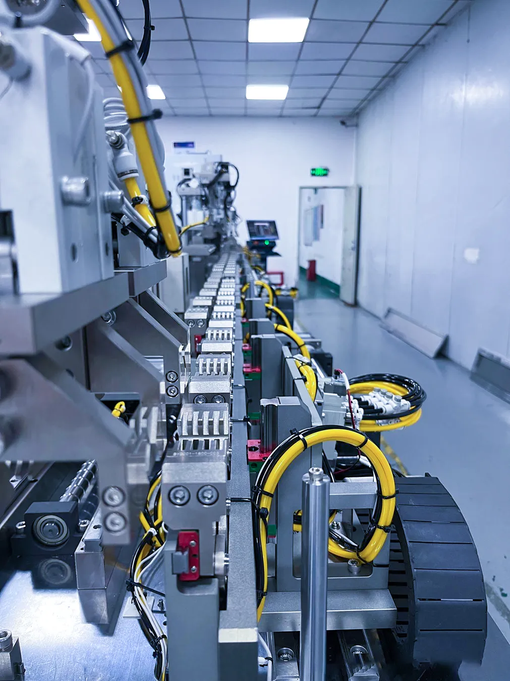
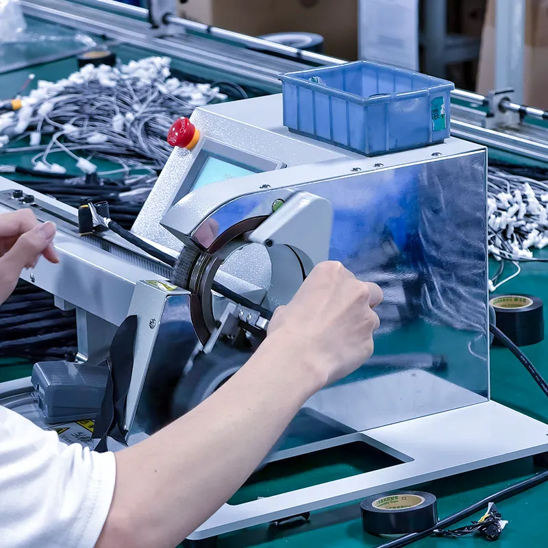
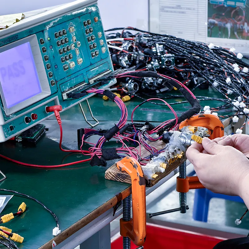
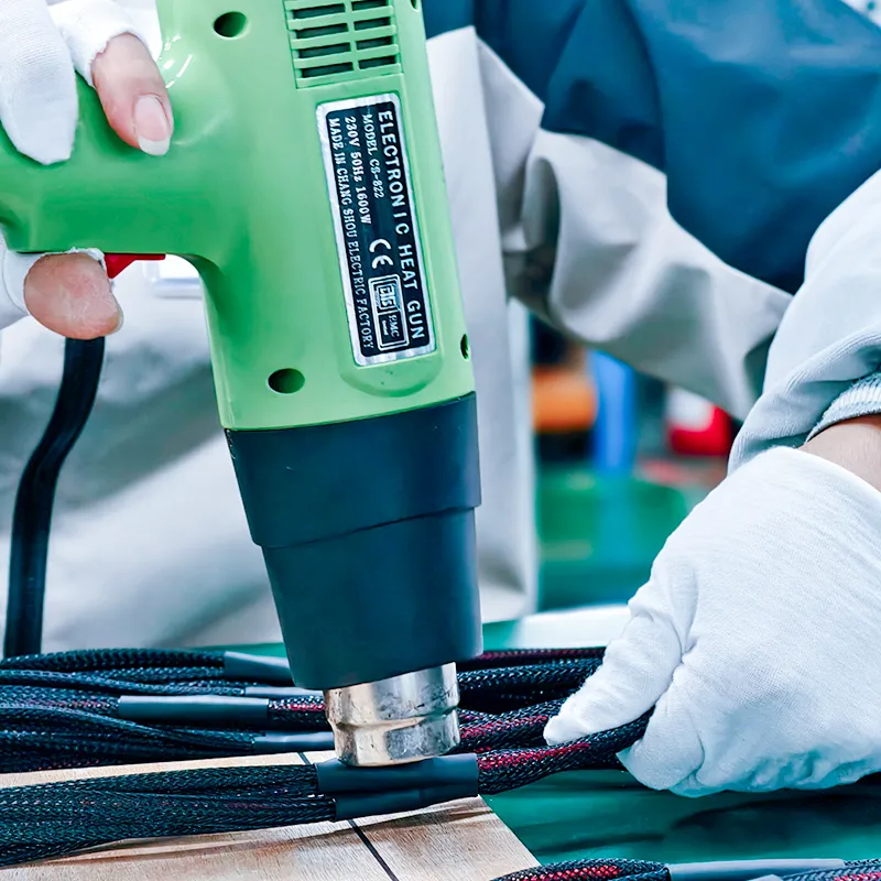
Display
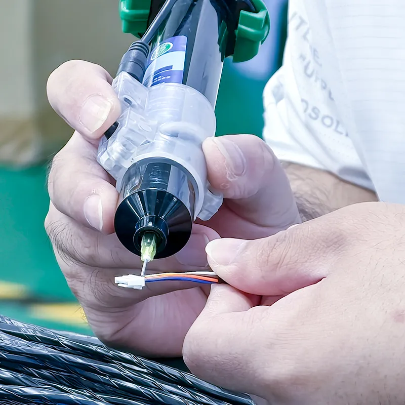
100% real on-site photos. Video inspection available upon request
100% real on-site photos. Video inspection available upon request
Common Buyer Questions
Cable strain relief is the set of design and manufacturing features that keep pull, bend, and handling loads away from the electrical termination. It can involve overmolds, boots, heat shrink, glands, clamps, routing features, or combined methods depending on the environment and failure mode.
We choose by actual use conditions. Overmolding is strong when you need integrated shape, grip, and repeat sealing. Adhesive-lined heat shrink works well for lower-cost sealed transitions and branch protection. Cable glands fit enclosure entries where thread standards, serviceability, and ingress ratings matter. Many projects use more than one method across the same assembly.
Yes, when the selected method seals the cable entry path instead of only resisting pull. Overmolds, adhesive-lined heat shrink, glands, and compound-backed transitions can all improve environmental performance when they are matched to the connector or enclosure design and verified in testing.
Yes. Validation depends on the program risk, but it often includes visual inspection, pull checks, bend review, continuity confirmation after handling, and environmental testing when sealing performance matters. The important point is defining those checks before volume starts.
The fastest quote includes the cable specification, connector or enclosure part numbers, target sealing level, expected pull or flex conditions, operating environment, quantity forecast, and any known failure history. Drawings, photos, and sample parts help when the geometry is not obvious from the BOM alone.
No. It matters anywhere cable handling can stress the termination, including medical leads, consumer devices, telecom equipment, machine wiring, outdoor assemblies, and serviceable field products. The method changes by application, but the need to protect the exit zone is common across industries.